The VIC (II) is the PPU of the C64. It has different modes it can be used in, and several functionalities that we will cover in the later chapters. For now, we only care about getting the first graphical output, so we will only get the Textmode (rudimentarily) working for now.
The C64 has a resolution of 320×200 pixels, and a border. The inner frame is where all the magic happens. The border, generally speaking, is always set to a single color (Yes, there are hacks that can mess with the border, but for simplicitys sake, we will try to keep it simple for now), and it’s width is variable, depending on the output screen.

In Textmode, the screen is divided into 40×25 (or 40×24, by selection) characters. These characters are read from CHRROM, that we loaded up in the last chapter.

The VIC itself reads from the full 64k of RAM, even the RAM below our ROM modules, like KERNAL, CHRROM, I/O etc. So every read from the VIC will read from the RAM directly, ignoring the ROMs. But, the VIC can only see a 16k window at once. So, we have to tell the VIC, which window we want to select.
 writes to $DD00 (CIA-2), lower 2 bits
--------------------------
 %00, 0: Bank 3: $C000-$FFFF
 %01, 1: Bank 2: $8000-$BFFF
 %10, 2: Bank 1: $4000-$7FFF
 %11, 3: Bank 0: $0000-$3FFF (Default)
This setting is not done directly by the VIC itself, but by the CIA 2. This is another complex part of the C64, that will be covered very soon. For now, all we need to know is, that writes to 0xdd00 (a register of the CIA 2) will set the VIC memory window.
In Textmode the indices of the characters are stored at 0x400 (default, relative) of the current memory window. So, we can just go through the adresses from 0x400 to 0x43e8, to read all the character of our (inner) window.
With these indices, we can then pick the correct character from CHRROM and display it.
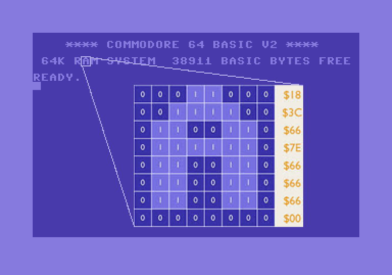
A character in CHRROM takes up 8 bytes and is stored as follows:

My following rendering routine is created, so we can render by line, that’s why we have to jump from character to character, to get the correct bytes.
uint16_t chrrom = 0x400 * (readFromMemByVIC(0xd018) & 0b1110);
uint16_t screen_ram = 0x400 * ((readFromMemByVIC(0xd018) & 0b11110000) / 0x10);
uint8_t offset_x = readFromMemByVIC(0xd016) & 0b111;
uint8_t border_mode_offset = (readFromMemByVIC(0xd016) & 0b1000) ? 0 : 16;	//	38 cols if off, 40 cols if on
uint16_t colorram = 0xd800;
for (int i = 0; i < 402; i++) {

	//	inside
	uint16_t offset = ((j - 40) / 8) * 40 + (i - 40) / 8;
	uint8_t char_id = readFromMemByVIC(screen_ram + offset);

	uint8_t row = readFromMemByVIC(chrrom + (char_id * 8) + ((j-40) % 8));
	uint8_t color = readFromMemByVIC(colorram + offset);

	uint8_t bg_color = readFromMemByVIC(0xd021);
	VRAM[(j * 402 * 3) + ((i + offset_x) * 3)] = ((row & (1 << (7 - (i - 40) % 8))) > 0) ? COLORS[color][0] : COLORS[bg_color][0];
	VRAM[(j * 402 * 3) + ((i + offset_x) * 3) + 1] = ((row & (1 << (7 - (i - 40) % 8))) > 0) ? COLORS[color][1] : COLORS[bg_color][1];
	VRAM[(j * 402 * 3) + ((i + offset_x) * 3) + 2] = ((row & (1 << (7 - (i - 40) % 8))) > 0) ? COLORS[color][2] : COLORS[bg_color][2];

	//	border
	uint16_t border_color = readFromMemByVIC(0xd020);
	if (i <= (39 + border_mode_offset) || i >= (360 - border_mode_offset) || j <= 39 || j >= 240) {
		VRAM[(j * 402 * 3) + (i * 3)] = COLORS[border_color][0];
		VRAM[(j * 402 * 3) + (i * 3) + 1] = COLORS[border_color][1];
		VRAM[(j * 402 * 3) + (i * 3) + 2] = COLORS[border_color][2];
	}
}
So, this code covers a little more than I described to far. It also draws a 40px border left, right, top and bottom. Also, the location of the CHRROM, and the location of the screen RAM are selected by 0xd018.
Also, we implemented horizontal scrolling right away (offset_x), and the option to select 40col or 38col mode (border_mode_offset).
Since we don’t want to have black and white characters, we also (for now the last thing) implemented the default Color Palette. The C64 offers a palette of 16 colors for basic stuff.

For your simplicity, I wrote down the color codes, change / improve as you like.
const unsigned char COLORS[16][3] = {
	{0x00, 0x00, 0x00},
	{0xff, 0xff, 0xff},
	{0x81, 0x33, 0x38},
	{0x75, 0xce, 0xc8},
	{0x8e, 0x3c, 0x97},
	{0x56, 0xac, 0x4d},
	{0x2e, 0x2c, 0x9b},
	{0xed, 0xf1, 0x71},
	{0x8e, 0x50, 0x29},
	{0x55, 0x38, 0x00},
	{0xc4, 0x6c, 0x71},
	{0x4a, 0x4a, 0x4a},
	{0x7b, 0x7b, 0x7b},
	{0xa9, 0xff, 0x9f},
	{0x70, 0x6d, 0xeb},
	{0xb2, 0xb2, 0xb2}
};
So, with our characters that we are about to print, we also have a correlating memory range for color, the Color RAM. The Color RAM is another oddity, because the VIC can see it, no matter in which memory window it works right now (it’s wired directly to this part of the RAM). The location therefore always is at 0xd800 up to 0xdbff.
When we successfully implemented all of the above, we should now be able to see the BASIC screen. The C64 takes 3-4 seconds to boot up (for me, in MSVC Debug mode), so don’t close right away if you happen to see a black screen.

This is a beautiful sight, right? But, if you have any experience with the C64, you will notice that there is no cursor (or there is a cursor, but it’s not blinking). This is, because we haven’t implemented any timers yet. Timers are part of the two CIA chips. CIA stands for “Complex Interface Adapter”, and has an important role, and that is why we will dedicate the next chapter to them.

Comments