A big part of the C64’s charme is coming from its sound chip, the SID – Sound Interface Device. It is able to play 3 separate voices, each of them has multiple waveforms, filters and extra features, that we will cover on this page.
Timing & Implementation
To be able to get a proper timing, we need to know a few numbers and figures.
CLOCK_PAL  =  985248 Hz
CLOCK_NTSC = 1022727 Hz

Sample Rate: 44100 Hz

Use sample every ~22 ticks (PAL)
Use sample every ~23 ticks (NTSC)
#define SAMPLE_STEPS 22
#define CLOCK_RATE 985250
This will bring us in the ballpark of being accurate with the time. We can still modify the sample rate and the sample steps later on.
void SID_init() {
	SDL_setenv("SDL_AUDIODRIVER", "directsound", 1);

	// Open our audio device; Sample Rate will dictate the pace of our synthesizer
	SDLInitAudio(44100, 1024);

	if (!SoundIsPlaying)
	{
		SDL_PauseAudio(0);
		SoundIsPlaying = true;
	}

	//	init channels
	channels.push_back(Channel());
	channels.push_back(Channel());
	channels.push_back(Channel());

	//	set channels to sync to, when SYNC bit is set
        //      and to be synced from when RING bit is set
	channels[2].setSyncToChannel(&channels[0]);
	channels[0].setSyncToChannel(&channels[1]);
	channels[1].setSyncToChannel(&channels[2]);
	channels[0].setSyncFromChannel(&channels[2]);
	channels[1].setSyncFromChannel(&channels[0]);
	channels[2].setSyncFromChannel(&channels[1]);
}
So with our initial SDL setup and the channels set up as well, we can now have a proper function to tick through the channels.
void SID_step() {
	if (++res_count >= SAMPLE_STEPS) {
		res_count = 0;

		//	tick channels
		channels[0].tick(volume);
		channels[1].tick(volume);
		channels[2].tick(volume);

		//	play last 100 samples of all channels
		if (channels[0].buffer.size() >= 100 && channels[1].buffer.size() >= 100 && channels[2].buffer.size() >= 100) {

			for (int i = 0; i < 100; i++) {
				float res = 0;
				if (PLAY_CHANNEL1)
					res += channels[0].buffer.at(i);
				if (PLAY_CHANNEL2)
					res += channels[1].buffer.at(i);
				if (PLAY_CHANNEL3)
					res += channels[2].buffer.at(i);
				Mixbuf.push_back(res / (PLAY_CHANNEL1 + PLAY_CHANNEL2 + PLAY_CHANNEL3));
			}
			//	send audio data to device;
			SDL_QueueAudio(1, Mixbuf.data(), Mixbuf.size() * sizeof(float));

			channels[0].buffer.clear();
			channels[1].buffer.clear();
			channels[2].buffer.clear();
			Mixbuf.clear();

			while (SDL_GetQueuedAudioSize(1) > 4096 * 8) {}
		}
	}
}
Waveforms
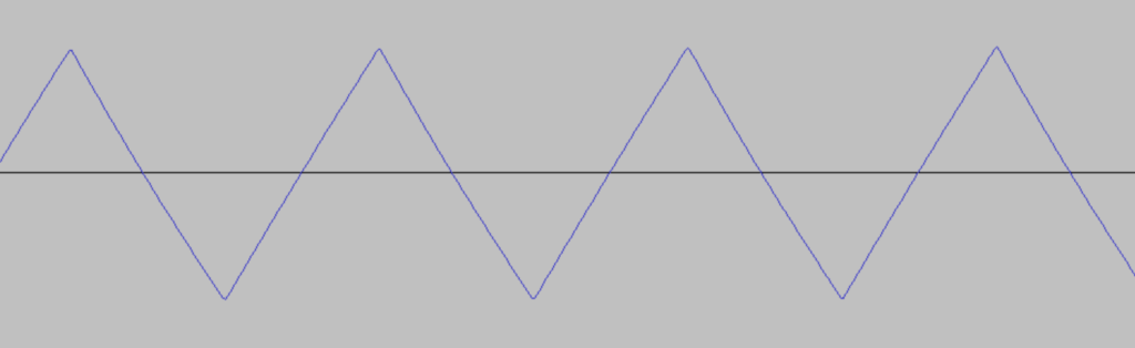
Triangle
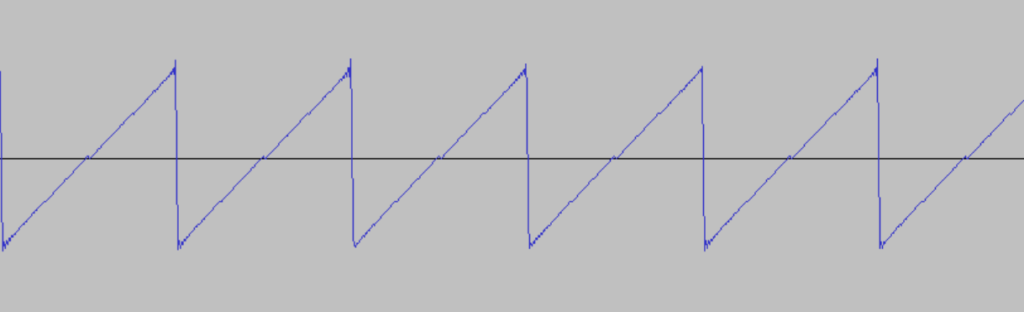
Sawtooth
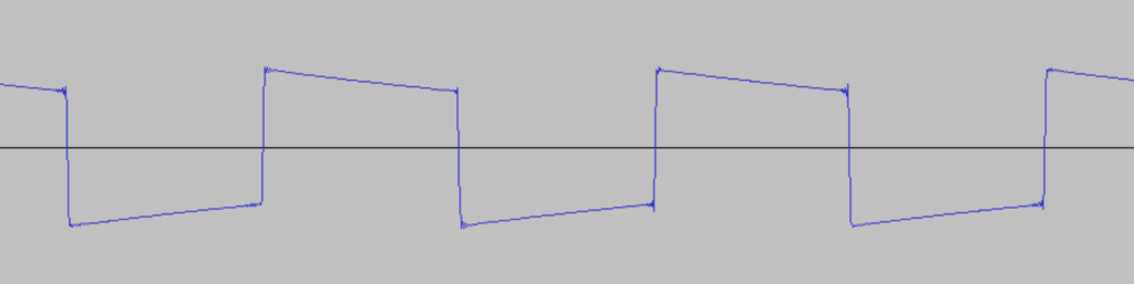
Pulse
Noise
Voices and addressing
The SID offers 3 Voices, each of which can make use of any of the above waveforms. To use those (and more) we need to be able to set a few settings, and therefore have the following addressing for SID and its components.
ADDR     Bit7  Bit6  Bit5  Bit4  Bit3  Bit2  Bit1  Bit0  Descr.   R/W
-----------------------------------------------------------------------

Voice 1:

D400     F7    F6    F5    F4    F3    F2    F1    F0    FREQ LO  Write
D401     F15   F14   F13   F12   F11   F10   F9    F8    FREQ HI  Write
D402     PW7   PW6   PW5   PW4   PW3   PW2   PW1   PW0   PW LO    Write
D403     -     -     -     -     PW11  PW10  PW9   PW8   PW HI    Write
D404     Noise Pulse ///   /\/\  TEST  RING  SYNC  GATE  CONTROL  Write
D405     ATK3  ATK2  ATK1  ATK0  DCY3  DCY2  DCY1  DCY0  ATK/DCY  Write
D406     STN3  STN2  STN1  STN0  RLS3  RLS2  RLS1  RLS0  STN/RLS  Write

Voice 2:

D407     F7    F6    F5    F4    F3    F2    F1    F0    FREQ LO  Write
D408     F15   F14   F13   F12   F11   F10   F9    F8    FREQ HI  Write
D409     PW7   PW6   PW5   PW4   PW3   PW2   PW1   PW0   PW LO    Write
D40A     -     -     -     -     PW11  PW10  PW9   PW8   PW HI    Write
D40B     Noise Pulse ///   /\/\  TEST  RING  SYNC  GATE  CONTROL  Write
D40C     ATK3  ATK2  ATK1  ATK0  DCY3  DCY2  DCY1  DCY0  ATK/DCY  Write
D40D     STN3  STN2  STN1  STN0  RLS3  RLS2  RLS1  RLS0  STN/RLS  Write

Voice 3:

D40E     F7    F6    F5    F4    F3    F2    F1    F0    FREQ LO  Write
D40F     F15   F14   F13   F12   F11   F10   F9    F8    FREQ HI  Write
D410     PW7   PW6   PW5   PW4   PW3   PW2   PW1   PW0   PW LO    Write
D411     -     -     -     -     PW11  PW10  PW9   PW8   PW HI    Write
D412     Noise Pulse ///   /\/\  TEST  RING  SYNC  GATE  CONTROL  Write
D413     ATK3  ATK2  ATK1  ATK0  DCY3  DCY2  DCY1  DCY0  ATK/DCY  Write
D414     STN3  STN2  STN1  STN0  RLS3  RLS2  RLS1  RLS0  STN/RLS  Write

Filter:

D415     -     -     -     -     -     FC2   FC1   FC0   FC LO    Write
D416     FC10  FC9   FC8   FC7   FC6   FC5   FC4   FC3   FC HI    Write
D417     RES3  RES2  RES1  RES0  FILEX FILT3 FILT2 FILT1 RES/FILT Write
D418     3 OFF HP    BP    LP    VOL3  VOL2  VOL1  VOL0  MODE/VOL Write

Misc.:

D419     PX7   PX6   PX5   PX4   PX3   PX2   PX1   PX0   POT X    Read
D41A     PY7   PY6   PY5   PY4   PY3   PY2   PY1   PY0   POT Y    Read
D41B     O7    O6    O5    O4    O3    O2    O1    O0    OSC3/RND Read
D41C     E7    E6    E5    E4    E3    E2    E1    E0    ENV3     Read

---------------------------------------------------------------------

Noise - Noise (waveform)
Pulse - Pulse (waveform)
///   - Sawtooth (waveform)
/\/\  - Triangle (waveform)
PW    - Pulse Width
ATK   - Attack (ADSR)
DCY   - Decay (ADSR)
STN   - Sustain (ADSR)
RLS   - Release (ADSR)
To be able to hear sound from a voice, it does need a frequency, it needs to have a waveform selected (at least one), and it needs to have its GATE bit set. The GATE bit will enable the ADSR-Envelope Generator, which will ultimately generate a sound.
For creating the basic waveforms I make a class and some member functions to run through. You already have seen the class Channel above in the set up function.
class Channel {

	private:
		float tickTriangle(float vol) {
			float step = ticks / (float)CLOCK_RATE;
			float value = (std::abs(0.5f - fmod((real_freq * step), 1.f)) * 4.0 * (-1.0f) + 1.0f) * vol;
			return value;
		}
		float tickSawtooth(float vol) {
			float step = ticks / (float)CLOCK_RATE;
			float value = fmod((step * real_freq), 1.0f) * vol;
			return value;
		}
		float tickPulse(float vol) {
			float step = fmod((ticks / (float)CLOCK_RATE * real_freq), 1.0f);
			float value = (step <= ((float)pulse_width / 4096.0)) ? -1.0 * vol : 1.0 * vol;
			return value;
		}
		float tickNoise(float vol) {
			float step = ticks / (float)CLOCK_RATE;
			if (((int)(freq * step) / 1) != lfsr_step) {
				lfsr = ((lfsr << 1) & 0b11111111111111111111111) | (((lfsr >> 17) & 0b1) ^ ((lfsr >> 22) & 0b1));
				lfsr_step = (int)(freq * step) / 1;
			}
			u8 value = (((lfsr >> 22) & 1) << 7) | (((lfsr >> 20) & 1) << 6) | (((lfsr >> 16) & 1) << 5) | (((lfsr >> 13) & 1) << 4) | (((lfsr >> 11) & 1) << 3) | (((lfsr >> 7) & 1) << 2) | (((lfsr >> 4) & 1) << 1) | ((lfsr >> 2) & 1);
			return ((value - 128.f) / 255.f) * vol;
		}
		float tickSilence(float vol) {
			return 0.f;
		}

	public:
		//	config
		u32 ticks = 0;
		bool GATE = false;
		bool SYNC = false;
		bool RING = false;
		bool TEST = false;
		u16 real_freq = 0;						//	Real frequency
		u16 freq = 0x0000;						//	Register value
		u16 pulse_width = 0x0000;				//	Pulse width for Rectangle
		u8 attack = 0x00;
		u8 decay = 0x00;
		u8 sustain = 0x00;
		u8 release = 0x00;
		u8 pot_x = 0x00;
		u8 pot_y = 0x00;
		float ADSR_timer = 0.0f;
		ADSR_MODE ADSR_mode = ADSR_MODE::RELEASE;
		std::vector<float> buffer;
		Channel* syncTo_channel;
		Channel* syncFrom_channel;
		float (Channel::* process)(float) = &Channel::tickSilence;
		//	used for SYNC & RING
		float val = 0.0f;
		float prev_val = 0.0f;

		void tick(float vol) {

			//	handle SYNC (if set)
			val = sin(2 * pi * (ticks / (float)CLOCK_RATE) * real_freq);
			if (syncTo_channel->SYNC && ((prev_val < 0 && val >= 0) || (prev_val <= 0 && val > 0))) {
				syncTo_channel->ticks = 0;
			}
			prev_val = val;

			//	handle actual soundwave
			ticks = (ticks + SAMPLE_STEPS) % CLOCK_RATE;
			float adsr_vol = vol;
			ADSR_timer += ((float)SAMPLE_STEPS / (float)CLOCK_RATE) * 1000.f;
			switch (ADSR_mode)
			{
			case ADSR_MODE::ATTACK:
				adsr_vol = (ADSR_timer / ATTACK[attack]) * vol;
				if (ADSR_timer > ATTACK[attack]) {
					ADSR_mode = ADSR_MODE::DECAY;
					ADSR_timer = fmod(ADSR_timer, ATTACK[attack]);
				}
				break;
			case ADSR_MODE::DECAY:
				adsr_vol = vol - (( vol - ( vol * (sustain / 15.0))) * (ADSR_timer / DECAY[decay]));
				if (ADSR_timer > DECAY[decay]) {
					ADSR_mode = ADSR_MODE::SUSTAIN;
					ADSR_timer = 0.0f;
				}
				break;
			case ADSR_MODE::SUSTAIN:
				adsr_vol = vol * (sustain / 15.f);
				break;
			case ADSR_MODE::RELEASE:
 				adsr_vol = std::fmax((float)sustain - std::fmax((float)sustain * (ADSR_timer / RELEASE[release]), 0.0f), 0.0f) / 15.f;
				break;
			default:
				break;
			}

			//	process waveform
			float v = (this->*process)(pow(adsr_vol, 2));		//	pow 2/3 is a close-ish estimate to logarithim increase/decrease in volume

			//	handle RING (if set)
			if (RING) {
				v *= syncFrom_channel->val;
			}
			buffer.push_back(v);
			buffer.push_back(v);
		}

		void setNPST(u8 val) {
			//	if GATE is set, ATTACK is inited, else RELEASE is inited
			//	This is EDGE-SENSITIVE!
			if (!GATE && val & 0b0001) {
				ADSR_timer = 0.0f;
				ADSR_mode = ADSR_MODE::ATTACK;
			}
			else if(GATE && (val & 0b0001) == 0x0) {
				ADSR_timer = 0.0f;
				ADSR_mode = ADSR_MODE::RELEASE;
			}
			GATE = val & 0b0001;
			SYNC = val & 0b0010;
			RING = val & 0b0100;
			TEST = val & 0b1000;
			switch ((val >> 4) & 0b1111)
			{
			case 1:
				process = &Channel::tickTriangle;
				break;
			case 2:
				process = &Channel::tickSawtooth;
				break;
			case 4:
				process = &Channel::tickPulse;
				break;
			case 8:
				process = &Channel::tickNoise;
				break;
			default:
				process = &Channel::tickSilence;
				break;
			}
			//	if TEST is set, TICKS are reset, so the oscillator starts fresh
			if (TEST) {
				ticks = 0;
			}
		}

		void setAttackDecay(u8 val) {
			attack = (val >> 4) & 0b1111;
			decay = val & 0b1111;
		}

		void setSustainRelease(u8 val) {
			sustain = (val >> 4) & 0b1111;
			release = val & 0b1111;
		}

		void setFreqLo(u8 val) {
			freq = (freq & 0b1111111100000000) | val;
			real_freq = floor(freq * 0.0596);				//	set real frequency
		}

		void setFreqHi(u8 val) {
			freq = (freq & 0b0000000011111111) | (val << 8);
			real_freq = floor(freq * 0.0596);				//	set real frequency
		}

		void setPulseWidthLo(u8 val) {
			pulse_width = (pulse_width & 0b1111111100000000) | val;
		}

		void setPulseWidthHi(u8 val) {
			pulse_width = (pulse_width & 0b0000000011111111) | ((val & 0b1111) << 8);
		}

		void setSyncToChannel(Channel* channel) {
			syncTo_channel = channel;
		}

		void setSyncFromChannel(Channel* channel) {
			syncFrom_channel = channel;
		}
};
ADSR – Attack, Decay, Sustain, Release

The ADSR-Envelope generator can be used to create lots and lots of sounds, each with its own ring to it, its own characteristics. The ADSR gives you the freedom to choose values for the individual phases:
Attack
The Attack phase is the phase, where the amplitude rises from 0 to volume (set by writes to 0xD418). The value written to the attack part of the register dictates how long it will take to reach the maximum value (here volume).
(The lengths will be shown in a table a bit below)
It is activated by the GATE bit switched on. This is an edge-sensitive event.
Decay
The Decay phase is the phase where the amplitude will fall, from the volume level, to the sustain level. The value written to the decay part of the register dictates how long it will take to reach the sustain level. This phase starts as soon as the Attack phase ends.
Sustain
The Sustain phase is the phase where the current volume is held, for as long as the code dictates us. The value written to the sustain part of the register dictates the amplitude in the sustain phase (not the duration). This phase starts as soon as the Decay phase ends.
Release
The Release phase is the phase, where the volume, starting at sustain level, decreases to zero over time. The value written to the release part of the register dictates how long it will take to reach zero.
This phase starts as soon as the GATE bit is set to zero. This is an edge-sensitive event.
Timing
VALUE    ATTACK RATE      DECAY/RELEASE RATE
          Time/Cycle              Time/Cycle
- ------------------------------------------
0               2 ms                    6 ms
1               8 ms                   24 ms
2              16 ms                   48 ms
3              24 ms                   72 ms
4              38 ms                  114 ms
5              56 ms                  168 ms
6              68 ms                  204 ms
7              80 ms                  240 ms
8             100 ms                  300 ms
9             240 ms                  750 ms
10            500 ms                   1.5 s
11            800 ms                   2.4 s
12               1 s                     3 s
13               3 s                     9 s
14               5 s                    15 s
15               8 s                    24 s
Additional settings
Pulse width
When selecting the waveform Pulse, we need to make an additional setting to the frequency, and that is the pulse width, or also called duty cycle. Basically, this will tell the waveform, how much of it is supposed to be one / positive amplitude.
Since we have a 12 bit register for the pulse width, we can set the values very precise from 0 to full_length.
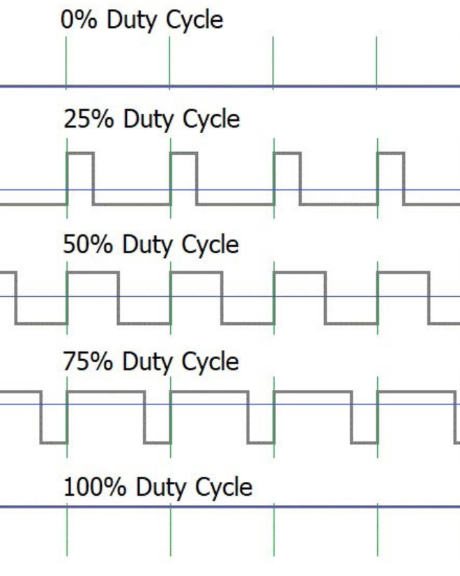
In the above image you can see a few settings of the Pulse Width and how they look like in the actual wave. Notice that the frequency is always the same, and it’s only the Pulse Width that is changed.
TEST-Bit
When writing 1 to the TEST-bit, the current cycle will be reset. That is all that it does.
//	if TEST is set, TICKS are reset, so the oscillator starts fresh
if (TEST) {
	ticks = 0;
}
SYNC-Bit
When enabled, the current voice will be hard-synched to it’s SYNC-channel / oscillator. On voice 1 it will be synched to voice 3, on voice 2 it will be synched to voice 1, and on voice 3 it will be synched to voice 2.
Hard-Synching means, whenever the sine-wave of the frequency of the SYNC-channel completes a cycle, the current voice is reset.
//	handle SYNC (if set)
val = sin(2 * pi * (ticks / (float)CLOCK_RATE) * real_freq);
if (syncTo_channel->SYNC && ((prev_val < 0 && val >= 0) || (prev_val <= 0 && val > 0))) {
	syncTo_channel->ticks = 0;
}
prev_val = val;
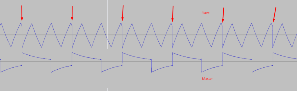
In the image you can see the SYNC-channel (e.g. voice 3, labelled Master) and the current channel (e.g. voice 1, labelled Slave). Whenever the SYNC-Channel completes a cycle, the current voice is reset. This can be used to create some unique sounds.
As you may already have noticed, this only works when there is a frequency set to the SYNC-channel. The frequency should be different than in the current channel, or you will not be able to hear any effect at all.
;*** TEST for SYNC bit ***

;*** Startadresse
*=$0801

;*** BASIC-Zeile
 !word main-2
 !word 2018
 !text $9E," 2062",$00,$00,$00

 !zone main
  main
  lda #$0f    ; set volume
  sta $d418

  ; channel 1

  lda #$a4    ; set freq lo
  sta $d400

  lda #$06    ; set freq hi
  sta $d401

  lda #$c4    ; set pw lo
  sta $d402

  lda #$16    ; set pw hi
  sta $d403

  lda #$11    ; set attack / decay
  sta $d405

  lda #$96    ; set sustain / release
  sta $d406

  lda #$13    ; set pulse, sync and gate
  sta $d404

  ; channel 3
  lda #$a4    ; set freq lo
  sta $d40e

  lda #$02    ; set freq hi
  sta $d40f

  lda #$01
  oops
  bne oops
The above code can test your implementation of the SYNC bit. Your output should be similar to the following:
RING-Bit
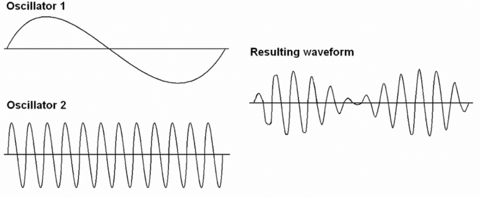
When enabled, the RING-Bit will apply ring-modulation to the current voice, also again with its SYNC-channel (same as before). Ring-modulation is nothing but multiplying the current voice with the sine-wave of the SYNC-channel. Again, the SYNC-channel needs to have a set frequency, other than the current voice, to create an audible effect.
//	handle RING (if set)
if (RING) {
	v *= syncFrom_channel->val;
}
;*** TEST for RING-Bit ***

;*** Startadresse
*=$0801

;*** BASIC-Zeile
 !word main-2
 !word 2018
 !text $9E," 2062",$00,$00,$00

 !zone main
  main
  lda #$0f    ; set volume
  sta $d418

  lda #$c4    ; set freq lo
  sta $d400

  lda #$16    ; set freq hi
  sta $d401

  lda #$c9    ; set ring freq lo
  sta $d40e

  lda #$00    ; set ring freq hi
  sta $d40f

  lda #$33    ; set attack / decay
  sta $d405

  lda #$9f    ; set sustain / release
  sta $d406

  lda #$15    ; set channel and gate, and RING
  sta $d404

  wait
  bne wait
The above code can test your implementation of the RING bit. Your output should be similar to the following:
Waveform tests
To be able to compare the emulation implementation to other emulators or even a real C64, I created a few tests with constant tones.
Triangle
;*** Triangle Constant Tone ***

;*** Startadresse
*=$0801

;*** BASIC-Zeile
 !word main-2
 !word 2018
 !text $9E," 2062",$00,$00,$00

 !zone main
  main
  lda #$08    ; set volume
  sta $d418

  lda #$c4    ; set freq lo
  sta $d400

  lda #$16    ; set freq hi
  sta $d401

  lda #$0f    ; set pulse width
  sta $d402
  sta $d403

  lda #$69    ; set attack / decay
  sta $d405

  lda #$fc    ; set sustain / release
  sta $d406

  lda #$11    ; set triangle channel and gate
  sta $d404

  oops
  bne oops
Sawtooth
;*** Sawtooth Constant Tone ***

;*** Startadresse
*=$0801

;*** BASIC-Zeile
 !word main-2
 !word 2018
 !text $9E," 2062",$00,$00,$00

 !zone main
  main
  lda #$08    ; set volume
  sta $d418

  lda #$c3    ; set freq lo
  sta $d400

  lda #$0a    ; set freq hi
  sta $d401

  lda #$69    ; set attack / decay
  sta $d405

  lda #$fc    ; set sustain / release
  sta $d406

  lda #$21    ; set sawtooth channel and gate
  sta $d404

  oops
  bne oops
Pulse
;*** Pulse Constant Tone ***

;*** Startadresse
*=$0801

;*** BASIC-Zeile
 !word main-2
 !word 2018
 !text $9E," 2062",$00,$00,$00

 !zone main
  main
  lda #$08    ; set volume
  sta $d418

  lda #$c4    ; set freq lo
  sta $d400

  lda #$09    ; set freq hi
  sta $d401

  lda #$0f    ; set pulse width
  sta $d402
  sta $d403

  lda #$69    ; set attack / decay
  sta $d405

  lda #$fc    ; set sustain / release
  sta $d406

  lda #$41    ; set pulse channel and gate
  sta $d404

  ldx #$69
  xloop
  bne xloop
Noise
;*** Noise Constant Tone ***

;*** Startadresse
*=$0801

;*** BASIC-Zeile
 !word main-2
 !word 2018
 !text $9E," 2062",$00,$00,$00

 !zone main
  main
  lda #$08    ; set volume
  sta $d418

  lda #$c4    ; set freq lo
  sta $d400

  lda #$09    ; set freq hi
  sta $d401

  lda #$69    ; set attack / decay
  sta $d405

  lda #$fc    ; set sustain / release
  sta $d406

  lda #$81    ; set noise channel and gate
  sta $d404

  ldx #$69
  xloop
  bne xloop
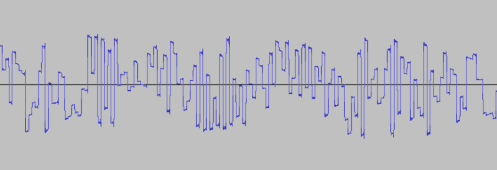
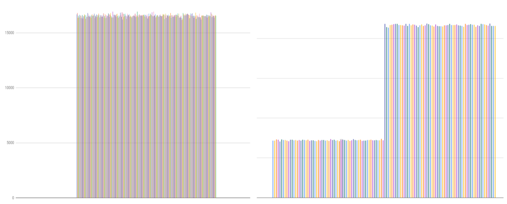
The noise channel is a 23-bit LFSR, that on shifting left, fills bit 0 with bit 17 XOR’ed with bit 22. You can see the implemenation at the beginning of the page, where all the waveforms are implemented. The output is generated from bits 22, 20, 16, 13, 11, 7, 4 and 2. You may be seeing other docs that tell you other output bits (e.g. 20, 18, 14, 11, 9, 5, 2 and 0) – those are wrong, and will give you a false distribution of numbers in the output of the LFSR.
Comments