Since the next test for the PPU will need some form of input (it’s the Mosaic test, and pressing buttons changes the value of the mosaic), we will now have to implement atleast the basic SNES controller.
auto-polling
Next to the individual reading of bits by setting certain bits and therefore pulsing the strobe to the controller (will be covered in later chapters, when we implement additional controllers like the mouse or the lightgun), the SNES offers auto-polling of the joypad data.
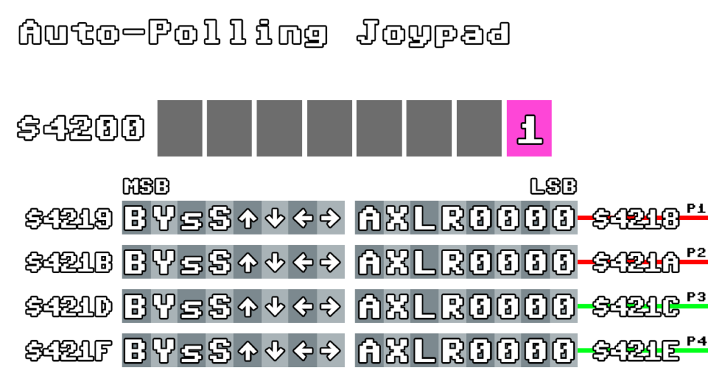
When bit 0 of $4200 is set, auto-polling is enabled. This is usually used when the game is played with a regular controller. There may be games that do manual polling though.
This auto-polling happens at the beginning of the VBlank period (between H=32.5 and H=95.5 of the first VBlank scanline). Usually it runs for a few cycles, but since we don’t need to emulate the serial transportation here (it doesn’t benefit fit us in any way), we can just immediately transfer the bits to the registers.
The description in the image is pretty much self-explanatory, the arrows show the directions on the D-Pad, A/B/X/Y are the buttons, L and R and the shoulder buttons, small-s is Select, capital-S is Start.
A set bit represents a pressed button, so when working with SDL2 again, we can implement a very simple keyboard-based solution to the controller implementation for now.
void setController1(uint8_t *SDL_keys) {
	resetController1();
	if (SDL_keys[SDL_SCANCODE_J])
		a = 1;
	if (SDL_keys[SDL_SCANCODE_K])
		b = 1;
	if (SDL_keys[SDL_SCANCODE_U])
		x = 1;
	if (SDL_keys[SDL_SCANCODE_I])
		y = 1;
	if (SDL_keys[SDL_SCANCODE_O])
		shoulder_r = 1;
	if (SDL_keys[SDL_SCANCODE_P])
		shoulder_l = 1;
	if (SDL_keys[SDL_SCANCODE_S])
		down = 1;
	if (SDL_keys[SDL_SCANCODE_A])
		left = 1;
	if (SDL_keys[SDL_SCANCODE_D])
		right = 1;
	if (SDL_keys[SDL_SCANCODE_W])
		up = 1;
	if (SDL_keys[SDL_SCANCODE_Q])
		select = 1;
	if (SDL_keys[SDL_SCANCODE_E])
		start = 1;
}

...

u16 readController1() {

	return (b << 15) | (y << 14) | (select << 13) | (start << 12) | (up << 11) | (down << 10) | (left << 9) |
		(right << 8) | (a << 7) | (x << 6) | (shoulder_l << 5) | (shoulder_r << 4);

}

...

void INPUT_stepJoypadAutoread() {
...
	//	for complexitys sake, we immediately read in the 16 bits to the registers, and skip the serial transmission
	writeToMem(readController1() & 0xff, 0x4218);
	writeToMem(readController1() >> 8, 0x4219);
...
};
Now we just have to call the function in the VBlank period.
void PPU_step(u8 steps) {

...
	if (RENDER_X == 0 && RENDER_Y == 241) {
		PPU_drawFrame();
		INPUT_stepJoypadAutoread();

	}
...

}
Comments