So far (including the color math chapter) it was enough to work with SDLs Blending mode functions, but it soon became clear to me that they would not suffice (or make it too hard or too expensive) to portrait all of the SNES’ PPUs capabilities. Mainly because of the Windows we have to implement now.
Windows
Windows are the ability to mask certain areas from the current layer. If you are familiar with Photoshop or any other advanced graphics tool you will already be familiar with the concept. A window (or mask) only holds 2 informations per pixel: visible or not visible.
The concept of the window looks something like this (white = visible, black = transparent):
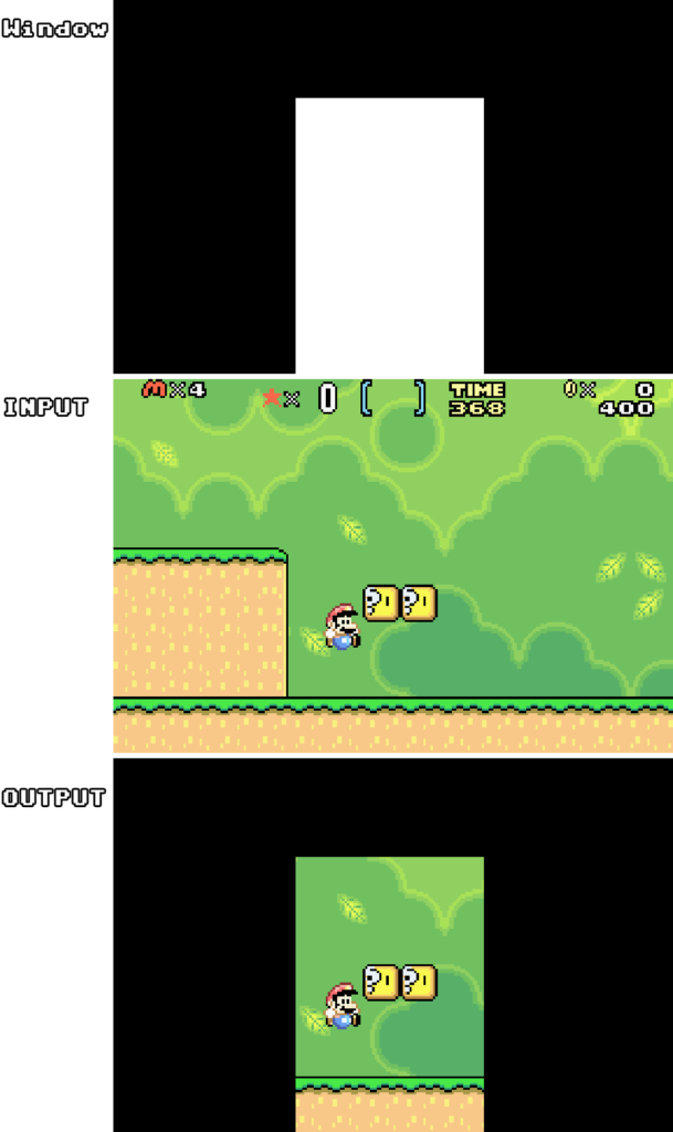
The parts of the input layer that are not visible, will become transparent, so the layer underneath it will become visible (unless it’s transparent as well, then this will continue on until the Backdrop (Main layers) or the Fixed Color (Sub layers).
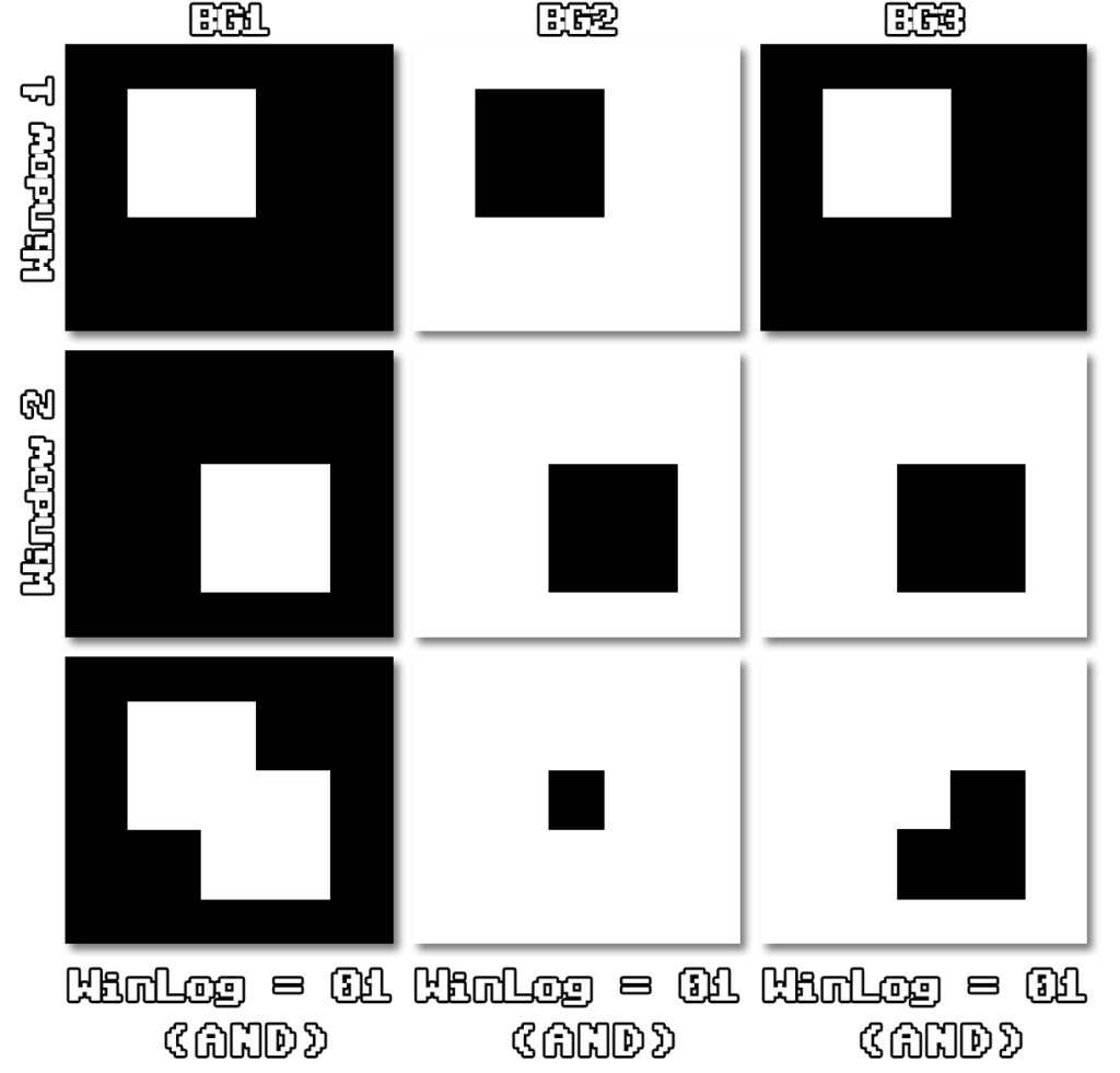
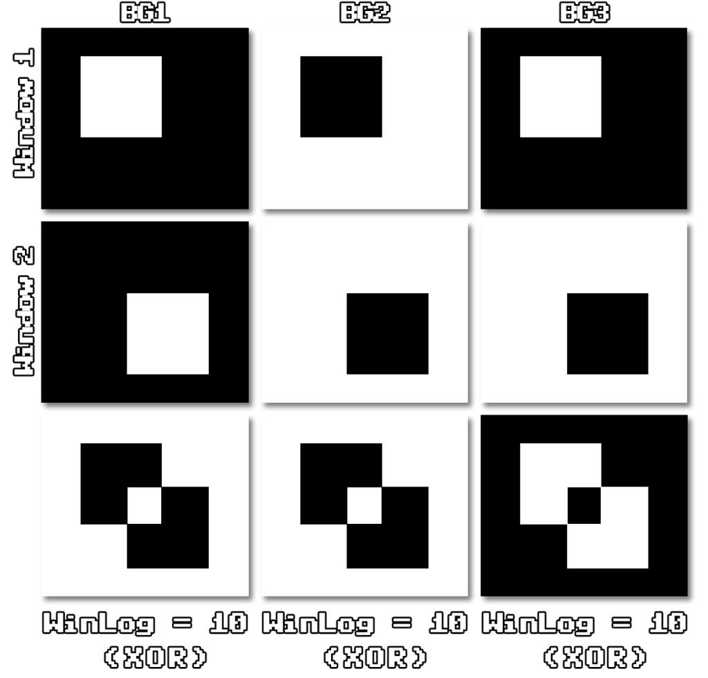
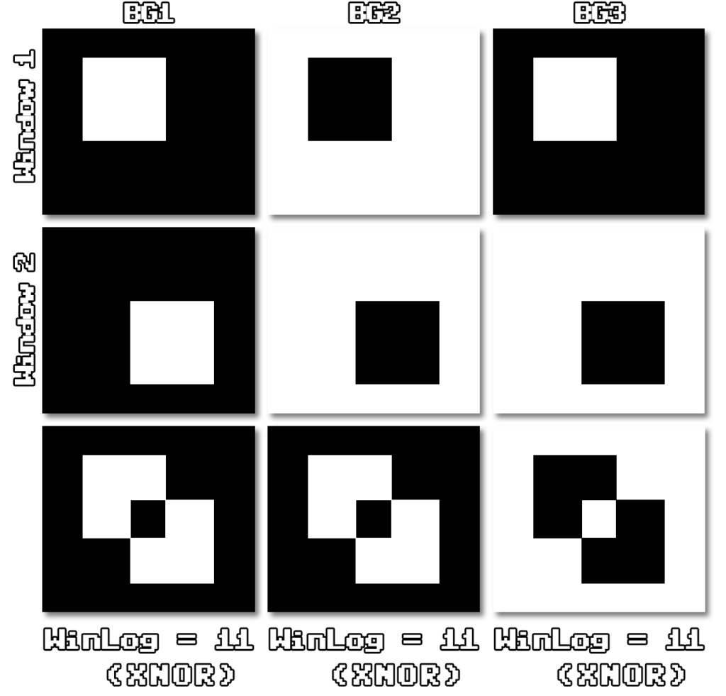
Each of the layers (Main and Sub) can have their own Window (the Main and the Sub of one layer share a window). Or better to say, Windows. The SNES offers 2 Windows per layer, which can be combined with each other, to form complex shapes. Each window can be enabled, disabled (WxEn registers), and even inverted (WxIO registers).
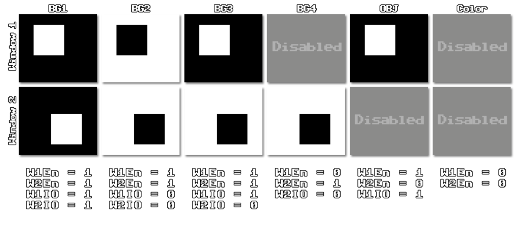
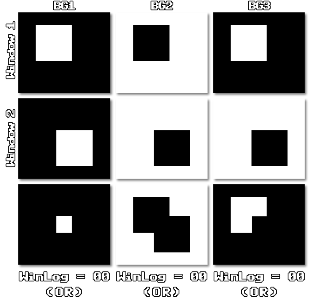
With the settings of the WinLog registers we are able to combine the two windows of each layer with OR, AND, XOR and XNOR, to create complex shapes for windows.
BG priorities
Another important part to mention before we make use of the Windows with out previous accomplishments is, that the background layers have different priorities, depending on the selected mode. We already know about the modes, but we will have to note what the order and the priorities of each BG modes are.
Mode0    Mode1    Mode2    Mode3    Mode4    Mode5    Mode6    Mode7

-        BG3.1a   -        -        -        -        -        -
OBJ.3    OBJ.3    OBJ.3    OBJ.3    OBJ.3    OBJ.3    OBJ.3    OBJ.3
BG1.1    BG1.1    BG1.1    BG1.1    BG1.1    BG1.1    BG1.1    -
BG2.1    BG2.1    -        -        -        -        -        -
OBJ.2    OBJ.2    OBJ.2    OBJ.2    OBJ.2    OBJ.2    OBJ.2    OBJ.2
BG1.0    BG1.0    BG2.1    BG2.1    BG2.1    BG2.1    -        BG2.1p
BG2.0    BG2.0    -        -        -        -        -        -
OBJ.1    OBJ.1    OBJ.1    OBJ.1    OBJ.1    OBJ.1    OBJ.1    OBJ.1
BG3.1    BG3.1b   BG1.0    BG1.0    BG1.0    BG1.0    BG1.0    BG1
BG4.1    -        -        -        -        -        -        -
OBJ.0    OBJ.0    OBJ.0    OBJ.0    OBJ.0    OBJ.0    OBJ.0    OBJ.0
BG3.0    BG3.0a   BG2.0    BG2.0    BG2.0    BG2.0    -        BG2.0p
BG4.0    BG3.0b   -        -        -        -        -        -
Backdrop Backdrop Backdrop Backdrop Backdrop Backdrop Backdrop Backdrop
This will ultimately end up as one of the very expensive parts of the code, we need to go through the currently selected order (set by the mode) for every pixel, to select the first opaque pixel. This is why transparency usually really tanks on performance, no matter which software we are talking about.
Reminder: The BG mode is set by register 0x2105
2105h - BGMODE - BG Mode and BG Character Size (W)
7   BG4 Tile Size (0=8x8, 1=16x16)
6   BG3 Tile Size (0=8x8, 1=16x16)
5   BG2 Tile Size (0=8x8, 1=16x16)
4   BG1 Tile Size (0=8x8, 1=16x16)
3   BG3 Priority in Mode 1 (0=Normal, 1=High)
2-0 BG  Screen Mode (0..7)
With this information we can make a sorting function for single pixels with code like this:
static PIXEL& getPixelByPriority(u8 bg_mode, PIXEL& bg1, PIXEL& bg2, PIXEL& bg3, PIXEL& bg4, PIXEL& obj, PIXEL& backdrop_fixedcolor, bool bg3_priority = false) {
	switch (bg_mode)
	{
	case 0:
		if (obj.priority == 3 && (obj.color & 1) == 1)	return obj;
		else if (bg1.priority == 1 && (bg1.color & 1) == 1)	return bg1;
		else if (bg2.priority == 1 && (bg2.color & 1) == 1)	return bg2;
		else if (obj.priority == 2 && (obj.color & 1) == 1) return obj;
		else if (bg1.priority == 0 && (bg1.color & 1) == 1)	return bg1;
		else if (bg2.priority == 0 && (bg2.color & 1) == 1)	return bg2;
		else if (obj.priority == 1 && (obj.color & 1) == 1) return obj;
		else if (bg3.priority == 1 && (bg3.color & 1) == 1)	return bg3;
		else if (bg4.priority == 1 && (bg4.color & 1) == 1)	return bg4;
		else if (obj.priority == 0 && (obj.color & 1) == 1) return obj;
		else if (bg3.priority == 0 && (bg3.color & 1) == 1)	return bg3;
		else if (bg4.priority == 0 && (bg4.color & 1) == 1)	return bg4;
		break;
	case 1:
		if (bg3.priority == 1 && bg3_priority && (bg3.color & 1) == 1) return bg3;
		else if (obj.priority == 3 && (obj.color & 1) == 1)	return obj;
		else if (bg1.priority == 1 && (bg1.color & 1) == 1)	return bg1;
		else if (bg2.priority == 1 && (bg2.color & 1) == 1)	return bg2;
		else if (obj.priority == 2 && (obj.color & 1) == 1) return obj;
		else if (bg1.priority == 0 && (bg1.color & 1) == 1)	return bg1;
		else if (bg2.priority == 0 && (bg2.color & 1) == 1)	return bg2;
		else if (obj.priority == 1 && (obj.color & 1) == 1) return obj;
		else if (bg3.priority == 1 && !bg3_priority && (bg3.color & 1) == 1) return bg3;
		else if (obj.priority == 0 && (obj.color & 1) == 1) return obj;
		else if (bg3.priority == 0 && (bg3.color & 1) == 1)	return bg3;
		break;
	case 2:
		if (obj.priority == 3 && (obj.color & 1) == 1)	return obj;
		else if (bg1.priority == 1 && (bg1.color & 1) == 1)	return bg1;
		else if (obj.priority == 2 && (obj.color & 1) == 1) return obj;
		else if (bg2.priority == 1 && (bg2.color & 1) == 1)	return bg2;
		else if (obj.priority == 1 && (obj.color & 1) == 1) return obj;
		else if (bg1.priority == 0 && (bg1.color & 1) == 1)	return bg1;
		else if (obj.priority == 0 && (obj.color & 1) == 1) return obj;
		else if (bg2.priority == 0 && (bg2.color & 1) == 1)	return bg2;
		break;
	case 3:
	case 4:
	case 5:
		if (obj.priority == 3 && (obj.color & 1) == 1) return obj;
		else if (bg1.priority == 1 && (bg1.color & 1) == 1)	return bg1;
		else if (obj.priority == 2 && (obj.color & 1) == 1) return obj;
		else if (bg2.priority == 1 && (bg2.color & 1) == 1)	return bg2;
		else if (obj.priority == 1 && (obj.color & 1) == 1) return obj;
		else if (bg1.priority == 0 && (bg1.color & 1) == 1)	return bg1;
		else if (obj.priority == 0 && (obj.color & 1) == 1) return obj;
		else if (bg2.priority == 0 && (bg2.color & 1) == 1)	return bg2;
		break;
	case 6:
		if (obj.priority == 3 && (obj.color & 1) == 1)	return obj;
		else if (bg1.priority == 1 && (bg1.color & 1) == 1)	return bg1;
		else if (obj.priority == 2 && (obj.color & 1) == 1) return obj;
		else if (obj.priority == 1 && (obj.color & 1) == 1) return obj;
		else if (bg1.priority == 0 && (bg1.color & 1) == 1)	return bg1;
		else if (obj.priority == 0 && (obj.color & 1) == 1) return obj;
		break;
	case 7:
		if (obj.priority == 3 && (obj.color & 1) == 1)	return obj;
		else if (obj.priority == 2 && (obj.color & 1) == 1) return obj;
		else if (bg2.priority == 1 && (bg2.color & 1) == 1)	return bg2;
		else if (obj.priority == 1 && (obj.color & 1) == 1) return obj;
		else if ((bg1.color & 1) == 1) return bg1;
		else if (obj.priority == 0 && (obj.color & 1) == 1) return obj;
		else if (bg2.priority == 0 && (bg2.color & 1) == 1)	return bg2;
		break;
	default: break;
	}
	return backdrop_fixedcolor;
}
Pixel Pipeline
Since the PPU is obviously a very complex unit, unless we would spend hours and hours mapping it out and optimizing it, we could potentially end up with a very expensive set of branches and edge cases. Luckily, we have all information available to emulate the actualy pixel pipeline. This is the way every pixel gets calculated in the hardware, which, when it’s shown in a single graphic, can make it much easier for us to see the connections between each registers and their effect on the actual calculation.
Huge props go out again to RGME (RetroGameMechanicsExplained) and his YouTube channel, for the great explanations here and the mail support while working on this.
Don’t get intimidated (like me at first), we will break it down in smaller bits.
Starting off with the window related stuff (everything connected to blue lines). We start at W1 (0x2126 / 0x2127) and W2 (0x2128 / 0x2129) where we check if the current pixel is within the left (0x2126 for W1 and 0x2128 for W2) and the right (0x2127 for W1 and 0x2129 for W2) borders, because only pixels inside the horizontal borders are used for windows.
After that we have a switch connected to W1En / W2En, followed by another switch for W1IO / W2IO. Both switches are controlled by the same registers, but different bits (depending on the Background).
W1En/W2En & W1IO/W2IO

Bit 2123h 2124h 2125h
7-6 BG2   BG4   MATH    Window-2 Area (0..1=Disable, 2=Inside, 3=Outside)
5-4 BG2   BG4   MATH    Window-1 Area (0..1=Disable, 2=Inside, 3=Outside)
3-2 BG1   BG3   OBJ     Window-2 Area (0..1=Disable, 2=Inside, 3=Outside)
1-0 BG1   BG3   OBJ     Window-1 Area (0..1=Disable, 2=Inside, 3=Outside)
You can see it’s always a pair of 2 bits, where the MSB defines W1En / W2En, which just shows if the Window is enabled at all, and the LSB defines W1IO / W2IO where we can invert the signal, basically inverting the Window.
These signals then get fed into WinLog which allows to combine the Windows via OR, AND, XOR and XNOR like seen earlier.
WinLog

Bit 212Ah 212Bh
7-6 BG4   -             Window 1/2 Mask Logic (0=OR, 1=AND, 2=XOR, 3=XNOR)
5-4 BG3   -             Window 1/2 Mask Logic (0=OR, 1=AND, 2=XOR, 3=XNOR)
3-2 BG2   MATH          Window 1/2 Mask Logic (0=OR, 1=AND, 2=XOR, 3=XNOR)
1-0 BG1   OBJ           Window 1/2 Mask Logic (0=OR, 1=AND, 2=XOR, 3=XNOR)
The output after WinLog, the combined Windows, is then fed to the Switches at TSW and TMW, where we are able to enable or disable specific layers for the Main– or Subscreen.
TSW (0x212F) / TMW (0x212E)

7-5     Not used
4   OBJ (0=Enable, 1=Disable)
3   BG4 (0=Enable, 1=Disable)
2   BG3 (0=Enable, 1=Disable)
1   BG2 (0=Enable, 1=Disable)
0   BG1 (0=Enable, 1=Disable)
-   Backdrop (Always enabled)
The output of this is then fed into the Switches that are connected to the Layer Data (everything connected to red lines). We will pick up on this later.
Behind WinLog you can see a single blue line going towards 2 big Switches, SubSW and MainSW. The registers are connected to a switch in the Layer Data at a point, where the data got trimmed down to a single color per Main- and Subscreen. So with MainSW and SubSW we have the ability to open or close this switch, basically allowing us to overwrite the calculated colors at this point with black (or alternatively with the Fixed Color, when Fix/Sub is set).
0x2130
Fix/Sub (Bit 1) / SubSW (Bit 4,5) / MainSW (Bit 6,7)

7-6  Force Main Screen Black (3=Always, 2=MathWindow, 1=NotMathWin, 0=Never)
5-4  Color Math Enable (0=Always, 1=MathWindow, 2=NotMathWin, 3=Never)
3-2  Not used
1    Sub Screen BG/OBJ Enable (0=No/Backdrop only, 1=Yes/Backdrop+BG+OBJ) 0    Direct Color (for 256-color BGs) (0=Use Palette, 1=Direct Color)
Now let’s start working from the Layer Data (red) towards the Switches we already talked about. The Layer Data is the actual pixel data on the Backgrounds, that is fed into the pixel pipeline. The first stop that we have to make is at the Switches connected to TM and TS, which are also a part of the Window. In these registers we can basically turn off layers completely, again for the Main– and the Subscreen.
TM (0x212C) / TS (0x212D)

7-5  Not used
4    OBJ (0=Disable, 1=Enable)
3    BG4 (0=Disable, 1=Enable)
2    BG3 (0=Disable, 1=Enable)
1    BG2 (0=Disable, 1=Enable)
0    BG1 (0=Disable, 1=Enable)
-    Backdrop (Always enabled
The output of that is connected to the Switches at TMW and TSW, that we already talked about. So, after those the lines reach the Main Priority Circuit and the Sub Priority Circuit, which do the ordering by priority, just as shown earlier. Since mode 1 offers the possibility to give BG3 extra priority, this is where BG3 PRI feeds in as well.
BG3 PRI (Bit 3)

7    BG4 Tile Size (0=8x8, 1=16x16)
6    BG3 Tile Size (0=8x8, 1=16x16)
5    BG2 Tile Size (0=8x8, 1=16x16)
4    BG1 Tile Size (0=8x8, 1=16x16)
3    BG3 Priority in Mode 1 (0=Normal, 1=High)
2-0  BG Screen Mode (0..7 = see below)
After the date got sorted by priority, we are left with a single color value (the first opaque pixel). The Mainscreen line is directly fed into the Switch with MainSW, which we covered already. The Subscreen line is connected to another Switch, that is controlled by Fix/Sub (which we also covered already), and only then fed into the SubSW Switch. The only thing left to note here is, that the Switch takes COLDATA as alternative input, which is simply the register we can set the Fixed Color with.
COLDATA (0x2132)

7    Apply Blue   (0=No change, 1=Apply Intensity as Blue)
6    Apply Green  (0=No change, 1=Apply Intensity as Green)
5    Apply Red    (0=No change, 1=Apply Intensity as Red)
4-0  Intensity    (0..31)
The format may look a bit weird if you’re used to RGBA etc. But it’s actually pretty simple.
void PPU_writeSubscreenFixedColor(u8 val) {
	bool r = ((val >> 5) & 1) == 1;
	bool g = ((val >> 6) & 1) == 1;
	bool b = ((val >> 7) & 1) == 1;
	u8 intensity = val & 0b11111;
	if (r) fixedcolor_pixel.color = (fixedcolor_pixel.color & 0b11111'11111'00000'1) | (intensity << 1);
	if (g) fixedcolor_pixel.color = (fixedcolor_pixel.color & 0b11111'00000'11111'1) | (intensity << 6);
	if (b) fixedcolor_pixel.color = (fixedcolor_pixel.color & 0b00000'11111'11111'1) | (intensity << 11);
}
So the single color values we receive out of this are fed into the Math Circuit. Before we can talk about this, we need to cover the the single yellow line we have. The line comes out of the Main Priority Circuit and is being fed into the Select Circuit, and only carries the information of which layer the pixel on our Mainscreen is from. So we know which layer had the first opaque pixel after sorting by priority.
The Select Circuit is controlled by MathEn which simply has setting to either use Color Math on a layer, or not.
MathEn (Bits 0-5) / HalfEn (Bit 6) / Add/Sub (Bit 7)

7  Color Math Add/Subtract (0=Add; Main+Sub, 1=Subtract; Main-Sub)
6  Color Math "Div2" Half Result (0=No divide, 1=Divide result by 2)
5  Color Math when Main Screen = Backdrop (0=Off, 1=On) ;\
4  Color Math when Main Screen = OBJ/Palette4..7 (0=Off, 1=On) ; OFF: Show
-  Color Math when Main Screen = OBJ/Palette0..3 (Always=Off)
3  Color Math when Main Screen = BG4 (0=Off, 1=On)
2  Color Math when Main Screen = BG3 (0=Off, 1=On)
1  Color Math when Main Screen = BG2 (0=Off, 1=On)
0  Color Math when Main Screen = BG1 (0=Off, 1=On)
The output of Select Circuit is fed into the Math Circuit, just as well as Add/Sub and HalfEn, which control if the math operation is an additon or subtraction, and if the result is supposed to be divided by 2 or not.
We are not quite done though!
There is another quirk, that is important to know, which was left out of the image, because it would have made it a lot more confusing. So, if both W1En and W2En are false, the output of the OR/AND/XOR/NAND will always be false. Also, the Switches connecting Window and Layer Data are forced to be closed. This is to ensure that the screen doesn’t go black, when both Windows are disabled.
And this is it, we are already at the end of our pixel pipeline and have finally deducted which pixel we have to display for the current X/Y position. This process will be repeated for every single pixel, on every single frame, so better write our code somewhat efficent so our performance drop (there will be one) is not too big.
const bool in_W1 = window.W1_LEFT <= RENDER_X && RENDER_X <= window.W1_RIGHT;
const bool in_W2 = window.W2_LEFT <= RENDER_X && RENDER_X <= window.W2_RIGHT;

bool BG1Mux = false;
bool BG2Mux = false;
bool BG3Mux = false;
bool BG4Mux = false;
bool OBJMux = false;
bool SELMux = false;
if (window.w1en[0] || window.w2en[0]) {
	BG1Mux = !window.winlog[0](( in_W1 ^ window.w1IO[0]), (in_W2 ^ window.w2IO[0]));
}
if (window.w1en[1] || window.w2en[1]) {
	BG2Mux = !window.winlog[1](( in_W1 ^ window.w1IO[1]), (in_W2 ^ window.w2IO[1]));
}
if (window.w1en[2] || window.w2en[2]) {
	BG3Mux = !window.winlog[2](( in_W1 ^ window.w1IO[2]), (in_W2 ^ window.w2IO[2]));
}
if (window.w1en[3] || window.w2en[3]) {
	BG4Mux = !window.winlog[3](( in_W1 ^ window.w1IO[3]), (in_W2 ^ window.w2IO[3]));
}
if (window.w1en[4] || window.w2en[4]) {
	OBJMux = !window.winlog[4](( in_W1 ^ window.w1IO[4]), (in_W2 ^ window.w2IO[4]));
}
if (window.w1en[5] || window.w2en[5]) {
	SELMux = !window.winlog[5](( in_W1 ^ window.w1IO[5]), (in_W2 ^ window.w2IO[5]));
}

const bool MainWinBG1 = BG1Mux && window.tmw[0];
const bool MainWinBG2 = BG2Mux && window.tmw[1];
const bool MainWinBG3 = BG3Mux && window.tmw[2];
const bool MainWinBG4 = BG4Mux && window.tmw[3];
const bool MainWinOBJ = OBJMux && window.tmw[4];
const bool SubWinBG1 = BG1Mux && window.tsw[0];
const bool SubWinBG2 = BG2Mux && window.tsw[1];
const bool SubWinBG3 = BG3Mux && window.tsw[2];
const bool SubWinBG4 = BG4Mux && window.tsw[3];
const bool SubWinOBJ = OBJMux && window.tsw[4];

//	get pixel (incl. priority) from current x/y
switch (BG_MODE_ID)
{
case 0: getPixel<0>(); break;
case 1: getPixel<1>(); break;
case 2: getPixel<2>(); break;
case 3: getPixel<3>(); break;
case 4: getPixel<4>(); break;
case 5: getPixel<5>(); break;
case 6: getPixel<6>(); break;
case 7: getPixel<7>(); break;
default: break;
}

//	pipe the window in, pixel again will become transparent of not enabled at this point
if(!(MainWinBG1 || (!window.w1en[0] && !window.w2en[0])) || !window.tm[0])
	main_pixel_bg1.color = 0;
else
	main_pixel_bg1 = src_pixel_bg1;
if (!(MainWinBG2 || (!window.w1en[1] && !window.w2en[1])) || !window.tm[1])
	main_pixel_bg2.color = 0;
else
	main_pixel_bg2 = src_pixel_bg2;
if (!(MainWinBG3 || (!window.w1en[2] && !window.w2en[2])) || !window.tm[2])
	main_pixel_bg3.color = 0;
else
	main_pixel_bg3 = src_pixel_bg3;
if (!(MainWinBG4 || (!window.w1en[3] && !window.w2en[3])) || !window.tm[3])
	main_pixel_bg4.color = 0;
else
	main_pixel_bg4 = src_pixel_bg4;
if (!(MainWinOBJ || (!window.w1en[4] && !window.w2en[4])) || !window.tm[4])
	main_pixel_obj.color = 0;
else
	main_pixel_obj = src_pixel_obj;
if(!(SubWinBG1 || (!window.w1en[0] && !window.w2en[0])) || !window.ts[0])
	sub_pixel_bg1.color = 0;
else
	sub_pixel_bg1 = src_pixel_bg1;
if (!(SubWinBG2 || (!window.w1en[1] && !window.w2en[1])) || !window.ts[1])
	sub_pixel_bg2.color = 0;
else
	sub_pixel_bg2 = src_pixel_bg2;
if (!(SubWinBG3 || (!window.w1en[2] && !window.w2en[2])) || !window.ts[2])
	sub_pixel_bg3.color = 0;
else
	sub_pixel_bg3 = src_pixel_bg3;
if (!(SubWinBG4 || (!window.w1en[3] && !window.w2en[3])) || !window.ts[3])
	sub_pixel_bg4.color = 0;
else
	sub_pixel_bg4 = src_pixel_bg4;
if (!(SubWinOBJ || (!window.w1en[4] && !window.w2en[4])) || !window.ts[4])
	sub_pixel_obj.color = 0;
else
	sub_pixel_obj = src_pixel_obj;

//	main priority circuit
PIXEL p_main = getPixelByPriority(BG_MODE_ID, main_pixel_bg1, main_pixel_bg2, main_pixel_bg3, main_pixel_bg4, main_pixel_obj, backdrop_pixel, BG3_PRIORITY);
PIXEL p_sub = (window.fixSub == 0) ? fixedcolor_pixel : getPixelByPriority(BG_MODE_ID, sub_pixel_bg1, sub_pixel_bg2, sub_pixel_bg3, sub_pixel_bg4, sub_pixel_obj, fixedcolor_pixel, BG3_PRIORITY);

p_main.color &= ~(u16)window.mainSW(SELMux);
p_sub.color &= ~(u16)window.subSW(SELMux);

u8 sr = (p_main.color >> 1) & 0b11111;
u8 sg = (p_main.color >> 6) & 0b11111;
u8 sb = (p_main.color >> 11) & 0b11111;
u8 dr = (p_sub.color >> 1) & 0b11111;
u8 dg = (p_sub.color >> 6) & 0b11111;
u8 db = (p_sub.color >> 11) & 0b11111;
if (window.mathEn[p_main.id]) {
	if (window.add_sub) {					//	Subtract
		sr = max(sr - dr, 0) >> window.halfEn;
		sg = max(sg - dg, 0) >> window.halfEn;
		sb = max(sb - db, 0) >> window.halfEn;
	}
	else {							//	Add
		sr = min(sr + dr, 0x1f) >> window.halfEn;
		sg = min(sg + dg, 0x1f) >> window.halfEn;
		sb = min(sb + db, 0x1f) >> window.halfEn;
	}
}

//	write to framebuffer
writeToFB(FULL_CALC, RENDER_X, RENDER_Y, 256, sr, sg, sb, 1);
Of course we test our sexy new pixel pipeline implementation with a few of kroms tests, and see, everything is working as expected.
Comments